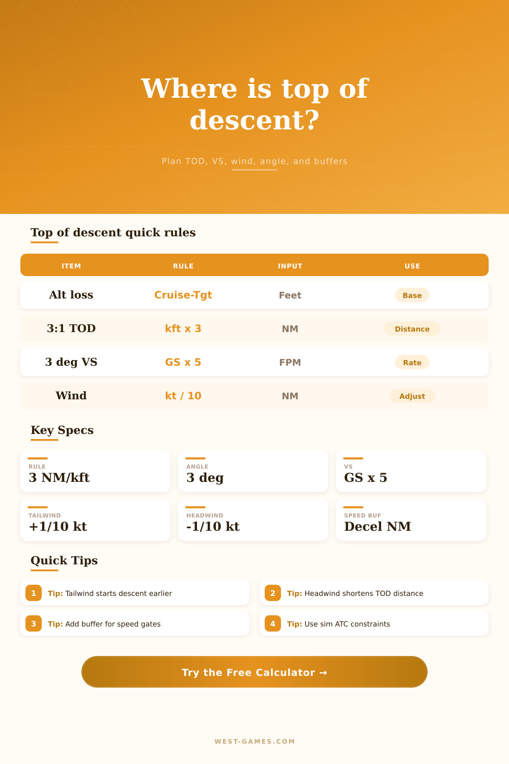
Flight Sim Top of Descent Calculator
Plan simulator-only top of descent distance, 3:1 rule distance, vertical speed, wind correction, descent angle, and speed restriction buffers before the arrival.
Formula breakdown
| Profile | Typical GS | Angle | Speed buffer | Best simulator use |
|---|---|---|---|---|
| Airliner | 260-310 kt | 3.0° | 1.0 NM / 10 kt | Managed VNAV and STAR planning |
| Regional jet | 230-280 kt | 3.1° | 0.9 NM / 10 kt | Short arrival paths and late vectors |
| Business jet | 280-340 kt | 3.2° | 1.2 NM / 10 kt | Fast cruise descents with speed control |
| Turboprop | 160-230 kt | 3.0° | 0.7 NM / 10 kt | Approach gates and runway transitions |
| GA trainer | 90-130 kt | 3.5° | 0.4 NM / 10 kt | Pattern entry and visual arrivals |
| Glider | 45-85 kt | 4.0° | 0.2 NM / 10 kt | Energy planning in soaring simulators |
| Calculation | Formula | Example input | Example result | Planning meaning |
|---|---|---|---|---|
| Altitude to lose | Current altitude - target altitude | 35,000 - 5,000 ft | 30,000 ft | Vertical distance available for descent |
| 3:1 distance | Altitude ft / 1000 x 3 | 30,000 ft | 90 NM | Classic top of descent baseline |
| 3 degree VS | Ground speed x 5 | 285 kt | 1,425 fpm | Quick rate for a 3 degree path |
| Descent angle | atan(alt ft / distance ft) | 30,000 ft / 102 NM | 2.7 to 3.0° | Path angle created by selected distance |
| Time to descend | Distance / ground speed x 60 | 102 NM / 285 kt | 21.5 min | Approximate time from TOD to target |
| Adjustment | Input direction | Rule used | Effect on TOD | Simulator note |
|---|---|---|---|---|
| Tailwind | Positive kt | +1 NM per 10 kt | Start earlier | Ground speed stays high, so you need more track miles |
| Headwind | Negative kt | -1 NM per 10 kt | Start later | Do not subtract below zero; keep terrain and restrictions in mind |
| Speed restriction | Current speed - target speed | Speed loss / 10 x decel NM | Adds buffer | Models drag and level segment needed to slow down |
| Extra buffer | Manual NM | Direct addition | Adds planning room | Useful for sim ATC, hold-downs, or idle descent limits |
| Angle override | Degrees | ft per NM = tan(angle) x 6076 | Changes computed VS | Compare the target path against the 3:1 rule |
| Scenario | Altitude lost | Baseline TOD | Typical VS | Key buffer |
|---|---|---|---|---|
| Airliner cruise to STAR fix | 28,000-34,000 ft | 84-102 NM | 1,300-1,600 fpm | Speed gate and tailwind |
| Turboprop to initial approach | 12,000-18,000 ft | 36-54 NM | 850-1,100 fpm | Approach speed reduction |
| GA visual descent | 2,000-6,000 ft | 6-18 NM | 450-700 fpm | Pattern entry altitude |
| Mountain step-down | 8,000-16,000 ft | 24-48 NM | 900-1,500 fpm | Terrain and crossing fixes |
| Online ATC speed gate | 10,000-30,000 ft | 30-90 NM | 1,000-1,600 fpm | 250 kt restriction below 10,000 ft |
Okay, you’re at thirty-five thousand feet. You’re up here cruising along minding your own business, and then comes the voice on headset: “When do you want to begin your descent? That’s it. That’s what all those simulator guy live for and fear.
And it isn’t some arbitrary dot on your chart. No, sir. It is not by any means just a mark. It marks the spot where your plane starts to climb. This determines if you will be on-speed and smooth or fighting the yoke and throttle with your flaps down. Miss it and what was going to be an uneventful arrival becomes a mad scramble.
How to Plan Your Descent
It’s actualy pretty easy math-wise. Why is it so hard for pilots to grasp intuitively while juggling everything else? Three-to-one (the three-to-one rule) forms the basis of all descent planning. Three nautical mile horizontal distance equals a one-thousand-foot drop in altitude. Why? It assumes you’re following a three-degree glide path. This angle provide passenger comfort and is standard for most instrument approaches.
Divide amount of altitude you want to shed by a thousand. Multiply by three. There’s your starting point. Enter your target and cruise altitudes into the calculator up top, and it’ll do the math for you. No more mental math when radio traffic heats up.
The one variable that will ruin even the best laid plan is wind. If there’s a tailwind, you go faster across the ground, which means for each foot you descend you’ve covered more ground. That requires starting your descent sooner to make up for additional track. If there’s a headwind, it has the reverse effect: you’ll go slower going forward so you can afford to delay your descent longer. Adding/subtracting this distance (depending on your wind component) is the function of tool and while it’s only a small correction in theory, it’s a huge deal in practice.
If you don’t start soon enough with a strong tailwind, you’ll be too high and too fast. You will have no choice but to use your speed brakes or ask someone to delay their flight so you can turn around.
There’s another wrinkle: speed limits. Before entering certain waypoints, ATC may ask that you reduce speed. There isn’t an “on/off” switch; you have to spend time slowing down. Because you can’t drop from 200 knots to zero in the same way you can descend, there needs to be a deceleration buffer. A safety margin is added into calculation based off how much speed you’ll want to lose within a nautical mile.
New pilots sometimes forget this; they concentrate so hard on getting their altitudes correct but then fly through the gate doing 200 knots instead of 180 as required. Maintaining a speed buffer show whether you are complying or not, which is what air traffic control requests when they give you a restriction.
It’s outlined on the page with the table of references (the table to the right). A general aviation trainer doesn’t descend like an airliner does. And a turboprop doesn’t descend like a general aviation trainer do either. Heavier airplanes will carry more energy. They need longer to bleed it off. Lighter airplanes will be able to lose altitude rapidly without covering as much ground. It is more about understanding your airplane’s energy state than the raw number itself.
In a small piston plane, you have less margin for error when it comes to terrain but also more freedom to maneuver yourself around. When you’re in a business jet simulator you have more momentum to deal with.
The tool automates some of those assumptions based on preset buttons. If you select an A320 IFR arrival it will fill in common speed buffers and descent angles for that type of aircraft. This saves having to guess and is a useful shortcut. From there you can adjust as needed based off the actual conditions at the time.
Perhaps the winds are heavier then predicted. Or perhaps you would of liked to give yourself an additional mile of buffer for a tricky approach. You can adjust for the real world, not a perfect vacuum.
At its core, this whole thing is all about managing energy. Time, kinetic energy, and potential energy are being traded. When done well, your descent plan goes easily. You’re on a nice gentle curve with a slow speed decrease approaching airport. Is it badly planned? Your descent is a bunch of jagged corrections that never seem to go anywhere.
Ideally you want the cruise-to-landing transition to feel natural. Create the habit by using tool. Make the math second nature by practicing it. And then, come flight time, you’ll know just when to put your nose down.